Studies on wind flow are received a huge interest in recent decades. Wind is known as a clean source of energy. Moreover, it plays a great role in urban ventilation to control air pollution. Therefore, wind flow simulations around single or complex buildings are raised up in recent years. My colleagues and I made several wind flow simulations. These simulations are conducted with OpenFOAM solver simpleFoam which is a stead-state solver. OpenFOAM supports a wide class of turbulence models. Different turbulence models are examined in these simulations to find the best result with experimental data. My experience shows kOmegaSST is the most suitable RANS turbulence model for simulation of wind flow.
A brief report of our simulation is presented below:
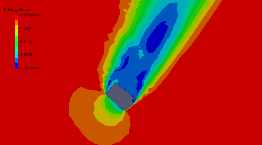
wind flow around simple geometries
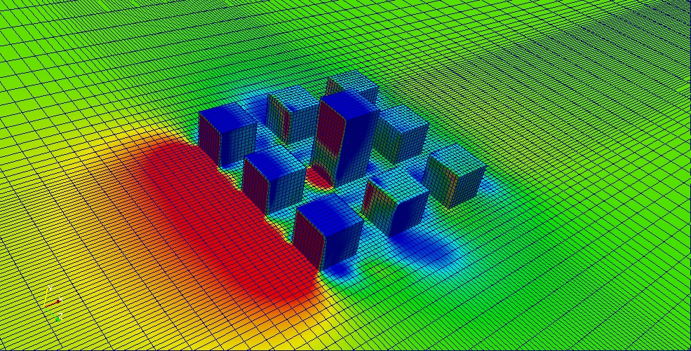
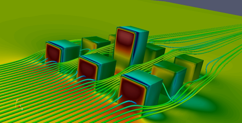
We made a simple building complex based on studies presented here (case C). The computational domain is created with Gambit software. It is easily imported to OpenFOAM with fluent3DMeshToFoam command. The inlet velocity profile is provided from wind tunnel data. The experimental data can be directly applied using timeVaryingMappedFixedValue as inlet boundary condition. The Slip or symmetryPlane boundry condition is usually considered for top (atmosphere) and sides patches. Out flow condition is applied at outlet means the velocity gradient and pressure is zero. Wall functions are used in ground and buildings patch for turbulent variables such as epsilon, omega, k and nut. The pressure contour and stream lines are shown below (Figure 1).
The detailed numerical simulation procedure is presented as book chapter in new edition of My book.
wind flow around wind catchers
A wind catcher (wind tower ) is a traditional Persian architectural element to create natural ventilation in buildings (Figure 2 ). Vast deserts exist in central regions of Iran which have hot and dry climate. The wind catcher can function in three ways to improve air ventilation and thermal comfort:
- directing airflow downward using direct wind entry
- directing airflow upwards using a wind-assisted temperature gradient
- directing airflow upwards using a solar-assisted temperature gradient
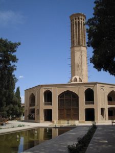
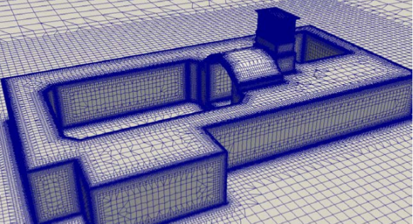
One of the most common uses of the wind catcher is to cool the inside of the buildings; it is often used in combination with courtyards as an overall ventilation and heat-management strategy. It is essentially a tall, capped tower with one face open at the top. This open side faces the prevailing wind, thus “catching” it, and brings it down the tower into the heart of the building to maintain air flow, then cooling the building interior. It does not necessarily cool the air itself, but rather relies on the rate of airflow to provide a cooling effect. Wind catchers tend to have one, four, or eight openings. The tower of the Mortaz house in the city center of Yazd / Iran which was our case study has four sided openings. The dimensions of computational domain are considered several times (usually more than 15 times) greater than larger spatial scale in buildings which is the height of wind tower. One of the numerical difficulty is proper mesh generation to resolve small openings regardless to the large dimensions of domain. The geometry of building is built in CAD software and and exported in STL format. The grid is created using OpenFOAM mesh generators blockMesh and snappyHexMesh (Figure 3). For velocity profile at inlet, the atmospheric boundary layer (ABL) boundary condition is applied.
The result of this study is presented in conference papers [1 , 2] .
wind flow in urban area
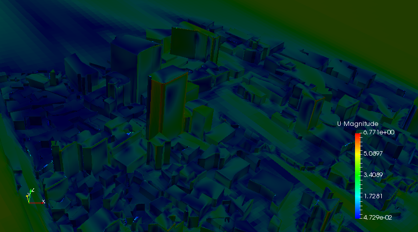
The pedestrians comfort in urban area specially near tall towers is interesting topic in the wind flow studies. In this research, wind flow is simulated in a region in the city of Port Louis the capital city of Mauritius. The CFD simulation is conducted with various turbulence models (kOmega and kEpsilon family) and the obtained results are compared with experimental data.
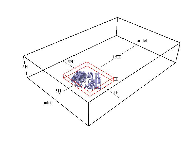
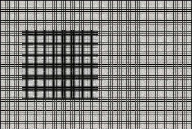
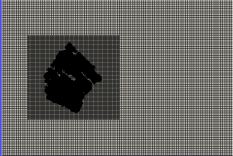
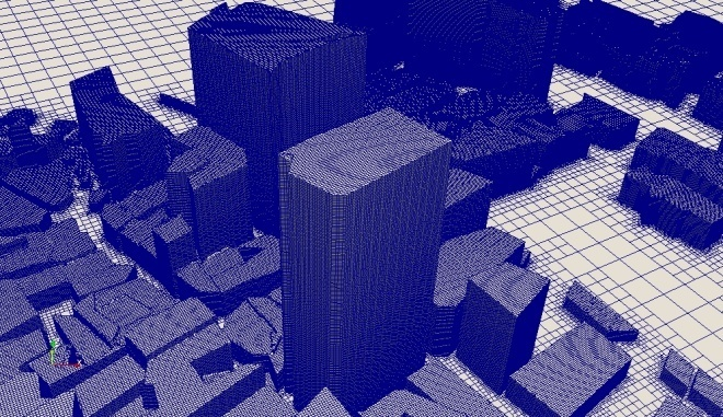
The schematic of computational domain is illustrated in Figure 4. The reference length (H) which is the height of highest building in our study is 110 m. The initial grid is generated with blockMesh. As the velocity gradient is higher near ground, The grid is stretching from ground to the atmosphere. The ratio of maximum cell height near atmosphere patch to minimum cell height near ground patch is 3. The grids in central region (nearby city location) are refined once with topSet, then final grid in figure is created with snappyHexMesh by adjusting the existing mesh to fit onto imported geometry file in STL format. The cells nears buildings are considered 5 times finer than the cells in initial grid. The gird generation process is shown in following slide show.

velocity contours of this simulation are shown below, extra information is published in the article [3].
Reference
- Hedayat, Z.H., Samkhaniani, N., Belmans, B., Ayatollahi, H., Wouters, I. and Descamps, F., 2015, December. Energy modeling and air flow simulation of an ancient wind catcher in Yazd. In 3rd International Congress on Civil Engineering, Architecture and Urban Development (pp. 29-31)
- Hedayat, Z.H., Samkhaniani, N., Belmans, B., Ayatollahi, H., Wouters, I. and Descamps, F., 2017. Energy performance analysis of solar-wind catchers under hot and dry climatic condition in Iran-Yazd. Int. J. of Solar Energy Research (JSER), 2(1).
- Dhunny, A.Z., Samkhaniani, N., Lollchund,M.R.,Rughooputh, S.D.D.V., 2018. Investigation of multi-level wind flow characteristics and pedestrian comfort in a tropical city. Urban Climate, Volume 24, (pp. 185–204)