In this post, i presented my simulation of free surface over cylindrical spillway using OpenFOAM solver (interFoam).
following steps are conducted for preparing case:
Create grid with OpenFOAM mesh generators
- generate base grid with blockMesh
- extract spillway from base grid and refine locally around spillway with snappyHexMesh
- extrude front patch to create 2D grid for simulation
The extrudeMeshDict setup is:
constructFrom patch;
sourceCase ".";
sourcePatches (front);

exposedPatchName back;

flipNormals false;

extrudeModel linearNormal;

nLayers 1;

expansionRatio 1.0;

linearNormalCoeffs
{
 thickness 0.1;
}
mergeFaces false;
mergeTol 0;
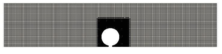
snappyHexMesh divides cells in z direction which is not suitable for 2D simulation. Thus extrudeMesh extrudes the front patch, so the final grid have only one cell in z direction. The final grid is shown below:
Simulation settings and result
- apply setFields to create non-uniform initial condition for volume fraction
- apply blank roughness using wall function nutRoughWallFunction via turbulence model
- run solver interFoam
- add appropriate functions into controlDict via swak4Foam for post processing. For example, the depth of water over spillway crest is calculated as follow:
depthOverCrest
 {
 type     swakExpression;
 valueType    set;
 verbose    true;
 setName    yb1;
 set
 {
 type    uniform;
 axis    y;
 start   ( 0 -0.175 -0.15 );
 end     ( 0  0.175 -0.15 );
 nPoints   60;
 }
 aliases  { alpha1  alpha.water; }
 expression "(alpha1 > 0.5) ? pos().y+0.175 :0";
 accumulations (max);
 interpolate   true;
 interpolationType   cellPoint ;
 outputControlMode   timeStep;
 outputInterval   1;
 }

For inlet, variableHeightFlowRate and variableHeightFlowRateInletVelocity is employed for alpha.water and velocity, respectively. These BCs consider the effect of downstream on the patch.
Hi Nima – I am curious to which BCs you used for this model.
Regards
JFM
i will edit the post and add the bc condition information